The WW2
Japanese 50mm Grenade Discharger was called a Knee Mortar by the US GIs
due to it’s curved base. They thought that the curve was placed around
the leg at the knee and fired that way. This caused numerous broken
legs due to the recoil of the weapon. The curve was so that it could
be used on the ground or on a round log as was used for field fortifications.
The Japanese military
used the grenade discharger to provide firepower at ranges between those
of the mortar & hand grenade. They were used in the close support
role both during the advance & in defense. They furnished firepower
that was heavy in comparison to their weight & mobility.
What was listed
as the first grenade discharger adopted by the Japanese in the WW2 US manual
“Japanese Mortars And Grenade Dischargers” has now been identified as a
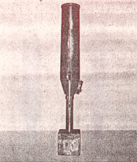
Chinese 50mm Type 27 (1937 in Chinese calendar). Captured Chinese
Dischargers were used by the Japanese in the Pacific causing the Technical
Intelligence people to assume they were Japanese. The Type 27 was
a simple tube with a bore of 50mm. The bottom had a chamber for the
gas generated when the charge was fired. There was a simple flat
circular gas port cap on the side of this chamber. The cap had 2
different sized holes in it. Rotating the cap gave the grenade 2
different ranges. The large hole was for short range & the smaller
for longer. There was a lever type trigger mounted in the shaft below
the chamber.
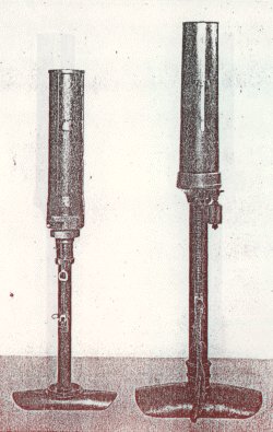
Type10 Discharger Type 89
Discharger
The 50mm Type 10
(1921) Grenade Discharger was the first one to have the curved base.
This was a smooth bore weapon and had an adjustable gas port at the bottom
of the barrel to control the range of the grenade. This discharger
fired the Type 10 & later Type 91 grenades with the booster screwed
into the base. It also fired pyrotechnic (flare) rounds. The
range with the Type 91 HE grenade was 65 to 175 meters depending on the
gas port setting.
Type 10 grenade Type 91 grenade with booster.
The 50mm Type 89
(1929) Grenade Discharger is the most common discharger used in WW2.
It had a rifled bore to increase both the range & accuracy of the weapon.
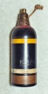
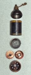
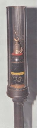
Type 89 shell. Type 89 shell disassembled.
The Type 89 shell
was designed with a copper rotating band. The base of the shell had
numerous holes drilled behind the rotating band. A powder charge
was placed in the copper can shown in the disassembled view. When
the primer was struck & the powder was ignited the pressure, acting
through these holes, forced the rotating band out into the rifling of the
barrel. At the same time the gas was vented out the holes shown in
the bottom of the base piece. This propelled the shell out of the
weapon. The white & yellow bands are the early color code used
by the Japanese. Sometime in 1942 it was changed to a central yellow
band. The red band just below the fuse indicates that it has an explosive
filling. This was used on both early & late color codes.
Incendiary & phosphorus smoke grenades were also fired from the Type
89 discharger.
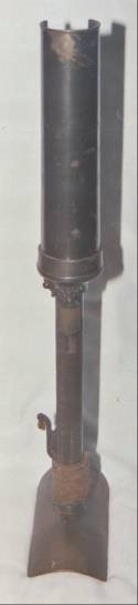
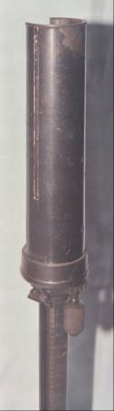
The Type 89 Grenade
Discharger had a lever type trigger coming out the side of the shaft below
the barrel. There was a knurled knob to adjust the range at the bottom
of the housing the barrel screwed into. A groove was machined down
the side of the barrel & this groove was filled with white paint.
This was a crude aiming device. Line the white line with what you
want to hit & then tip the discharger to what you think is a 45 degree
angle. A model was captured on Attu, the Aleutian Islands, Alaska,
that had a simple double bubble leveling device on the barrel. When
both bubbles were centered, the discharger was being held straight up &
down & was at a 45 degree angle. This was not found on most of
the Type 89 Grenade Dischargers.
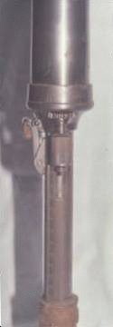
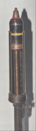
As mentioned before,
the range was controlled by a knurled knob. This knob was geared
to a screw that ran through the shaft below the barrel. As the knob
was turned, the screw turned. The screw was threaded through the
base so it went up and down as it turned. This raised & lowered
the shell in the barrel. When fired at the lowest setting, there
was a small area for the gas to go into & a longer distance for the
shell to travel before it left the barrel. This increased the velocity
& hence the range. When fired at it’s highest setting there was
a very large area for the gas to go into & a very short distance for
the shell to travel, hence a low velocity & short range.
As the shaft goes
up & down, the trigger goes with it. On both sides of the shaft
are marked the range of the shell at that setting. The markings are
for the Type 91 grenade on the right & the Type 89 Shell on the left.
If you are using a Type 89 shell and estimate that the target is 150 yards
away, you turn the knob until the trigger is lined up with the number 150
on the left hand scale.
So by holding the
discharger at a 45 degree angle & lining up the target with the white
line they could adjust the point of impact on the target by turning the
knurled knob to the range that they estimate the target to be at.
If they over shoot or under shoot, they just adjusted the knob to change
the range. The range scales on the shaft go from 120 meters to 650
meters for the Type 89 shell. As the Type 91 grenade does not engage
the rifling in the barrel there is considerable gas lost around it when
it is used. Consequently, the range scale for it is only 40 meters
to 190 meters.
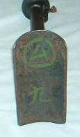
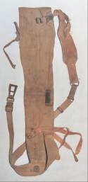
This discharger
is marked inside the base with a character in a circle that I would guess
is a unit marking. The number 9 below it would be the weapon number
in the unit. The discharger was issued with a cloth carrying case
that had a tool kit/spare parts pouch in a pocket. The pouch contains
a wrench and 4 spare springs tied together with a piece of twine, 2 ratchet
parts for the trigger, 2 firing pins & 4 screws. Both trigger
parts are serial numbered to the discharger as is the pouch & carrying
case.